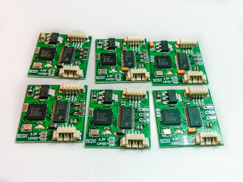
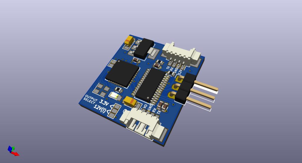
I’ve been working on new NT motor board design. I’ve reduced the size, made it more streamlined and added a regulator which will allow the board to work directly from 12V input. I also included a selectable voltage output by using a solder jumper, which will allow to pass the power to the next motor module or to pass 3.3V to the IMU module. This will save wires running through the gimbal.
I will fix some minor bugs and will run the board to production and will make preorders available in the shop.
Board dimensions 25mm x 27mm
Hello, and happy new year everyone!
I would like to announce that ENSYS is going on holiday from 2017.01.09 to 2017.01.17 so orders made at that time will be delayed.
Some of you may have received IMU units which are unable to calibrate properly. We found the cause that some older MPU6050 chips slipped in which have different accelerometer scaling register values, we did not notice this at the time, but all the new IMUs ordered should not have this problem.
To fix this you will have to update the firmware on your module. To do this you will need.
- A computer
- USB-TTL Serial adapter
You will need to download flashing utility from NXP here: http://www.
Connect NT Module TX -> USB-TTL RX and NT Module RX -> USB-TTL TX
then short the little solder bridge on the other side of the module (labelled BOOT on v2 modules), recommend using tweezers to do it, while the module is powered. You will need to just touch and short both pins.
Once done the LED should be very faintly lit, now the module is ready for flashing.

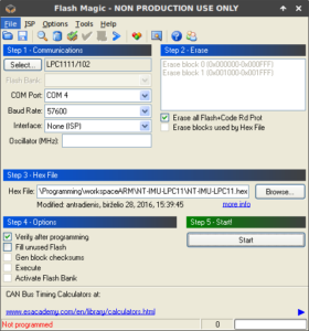
Open up Flash Magic utility. COM port will need to be set to your USB-TTL adapter. Baud rate 57600.
Load up the HEX file. Now it should program and verify the firmware.
If somehow you mess up, don’t worry. Short the solder bridge like before and then power up the module (while the solder bridge is shorted), the module will enter programming mode, and you can retry programming it.
Good luck!
Download: Contact us at info@ensys.lt for firmware files.


